Tumegacompra.com
Diy kit electronics LED circuit board kits LED light electronic components manufacturing diy kit spare parts student Laboratory
Diy kit electronics LED circuit board kits LED light electronic components manufacturing diy kit spare parts student Laboratory
Couldn't load pickup availability
SPECIFICATIONS
Brand Name: Gaqqee
Certification: CE
DIY Supplies: Electrical
Model Number: electronic components
Origin: Mainland China
Output Voltage: Diy kit electronics
Size: Electronic modules
Style: LED circuit board kits
Type: diy electronic
Diy kit electronics LED circuit board kits LED light electronic components manufacturing diy kit spare parts student Laboratory
Special attention: The working voltage and polarity recognition of the new blue LED is different from that of the traditional LED (the direction of the gap on the circuit board is opposite), please make the experiment accurate before installing.
Red, green, and yellow LEDs can work at 2-15V, and blue and white LEDs need 4-15V power supply. The higher the voltage, the faster the flashing and the greater the brightness.
The circuit board is processed with 1.5mm high-quality glass fiber board, the pad is super large, the wire is thick, there is no flying line, the component layout is beautiful, and the copper surface is sprayed with tin. Specially optimized design for practical training, it is convenient to withstand repeated desoldering and can improve the efficiency of use.
This circuit is especially suitable for beginners, with strong interest, obvious effect and low production difficulty. It is the material of choice for assembly practice and skill training.
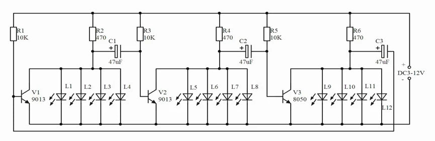
This circuit is a cyclic drive circuit composed of 3 transistors. Whenever the power is turned on, the three triodes will compete to be turned on first, but due to differences in components, only one triode will be turned on first. It is assumed that V1 is turned on first, then the collector voltage of V1 drops, causing the left end of the capacitor C2 to drop, close to 0V. Because the voltage across the capacitor cannot change suddenly, the base of V2 is also pulled to approximately 0V at this time, V2 is cut off, and the collector of V2 is high voltage, so the light-emitting diodes L5-L8 connected to it are lit. At this time, the high voltage of V2 increases the base voltage of V3 through the capacitor C3, and V3 will quickly turn on. Therefore, during this time, the collectors of V1 and V3 are low voltages, so only L5-L8 are lit , L1-L4, L9-L12 go out. But as the power supply charges C2 through the resistor R3, the base voltage of V2 gradually increases. When it exceeds 0.7V, V2 changes from an off state to an on state, the collector voltage drops, and L5-L8 goes out. At the same time, the falling voltage of the collector of V2 reduces the base voltage of V3 through the capacitor C3. V3 changes from on to off, the collector voltage of V3 rises, and L9-L12 are lit. Next, the circuit circulates according to the process described above, 3 groups of 12 light-emitting diodes will be lighted in turn, these LEDs are evenly arranged in a circle, and the light is continuously cycled to achieve the effect of flow. Changing the capacity of capacitors C1, C2, C3 can change the cycle speed, the smaller the capacity, the faster the cycle speed. Use 2 AA dry batteries for the power supply.
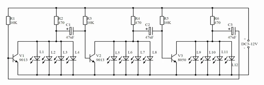
This circuit is a cyclic drive circuit composed of 3 transistors. When the power is turned on, due to the differences in the components of the three triodes (3 transistors that are not exactly the same are actually used), only one triode will be turned on first. Assuming that V1 is turned on first, the collector voltage of V1 drops, causing the left end of the capacitor C1 to drop, close to 0V. At this time, the base of V2 is also pulled to approximately 0V, V2 is cut off, the collector of V2 is at a high voltage, and L5-L8 are lit. At this time, the high voltage of V2 increases the base voltage of V3 through the capacitor C2, and V3 will quickly turn on. At this time, the collectors of V1 and V3 are low voltage, L5-L8 are lit, L1-L4, L9- L12 goes out. As the power supply charges C1 through the resistor R3 (actually C1 discharges), the base voltage of V2 gradually increases. When it exceeds 0.6V, V2 changes from the off state to the on state, and the collector voltage drops, L5-L8 Extinguished. At the same time, the falling voltage of the collector of V2 reduces the base voltage of V3 through the capacitor C2, V3 changes from on to off, the collector voltage of V3 rises, and L9-L12 are lit. Next, the circuit circulates according to the process described above, 3 groups of 12 light-emitting diodes will be lighted in turn, these LEDs are evenly arranged in a circle, and the light is continuously cycled to achieve the effect of flow. Changing the capacity of capacitors C1, C2, C3 can change the cycle speed. The power supply can use 2 AA dry batteries. (If a blue LED is used, the operating voltage should be increased to 4.5V, and pay attention to the polarity of the blue LED)